The first circuit I have created for my Pi is to simply flash an LED then, with this working, make a morse code machine.
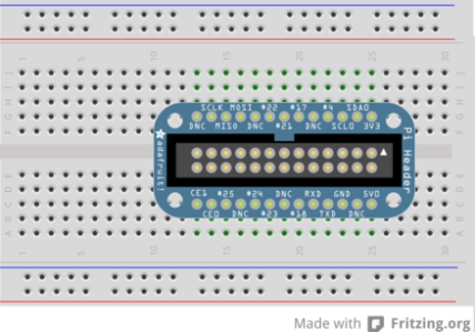
I use a Hobbytronics RPi Breakout board to break all of the GPIO pins out onto a breadboard. This is very similar to the Adafruit Cobbler but easier to get hold of in the UK. I find using this makes it easier to connect up to the right pin especially when I take the Pi away for other things. So, to start with I placed the breakout board on the Pi:
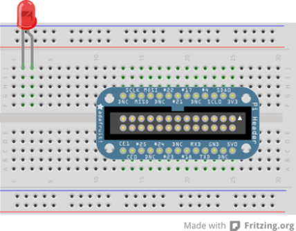
I then added an LED across two free rows:
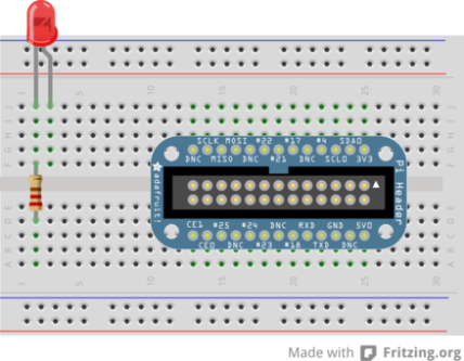
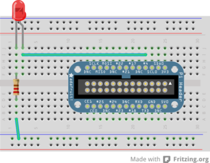
Followed by a 470ohm resistor from the short leg across the gap in the middle to another unused row:
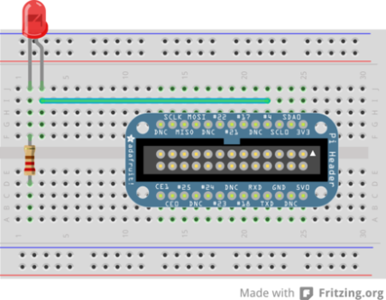
Now it’s time to connect up the wires. The first goes from GPIO pin 4 to the positive (long) leg of the LED:
Followed by a wire from the unconnected side of the resistor to the negative power rail:
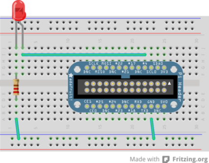
And finally a wire from the negative power rail to the ground (0V) pin:
This completes the circuit. NOTE: the LED must be connected the right way round and there must be a resistor in the circuit to prevent damage to the Pi.
Once the circuit is complete we need some code to operate the LED. I’m using Python with the RPi.GPIO library which comes a standard with the latest Raspian distribution.
First we import the RPi.GPIO library and give it an alias of GPIO and import the time library to time the flashes:
import RPi.GPIO as GPIO
import time
Next we tell the GPIO library to use the BCM numbering for the pins. These are the numbers printed on our breakout board (NOTE: I am using a Pi Rev 1 board. The rev 2 boards make a minor change to pin renumbering):
GPIO.setmode(GPIO.BCM)
Set up a variable to hold the number of the GPIO port we are going to use and initialise it to the port we plugged our circuit into. This prevents accidentally using the wrong port later in the code):
RED_LED_PORT = 4
Set the port up to be ready to receive output:
GPIO.setup(RED_LED_PORT, GPIO.OUT)
Set up an infinite while loop:
while True:
Send a signal to the port to turn the LED on:
GPIO.output(RED_LED_PORT, True)
Wait for half a second (if we didn’t have this the LED would flash so fast it would appear always on):
time.sleep(0.5)
Turn the LED off and wait for another half second:
    GPIO.output(RED_LED_PORT, False)
    time.sleep(0.5)
This completes our simple programme. The complete code is as follows:
import RPi.GPIO as GPIO
import time
GPIO.setmode(GPIO.BCM)
RED_LED_PORT = 4
GPIO.setup(RED_LED_PORT, GPIO.OUT)
while True:
    GPIO.output(RED_LED_PORT, True)
    time.sleep(0.5)
    GPIO.output(RED_LED_PORT, False)
    time.sleep(0.5)
Next time I’ll post the code for making this circuit flash messages in morse code.
I can’t understand it – haven’t got a rasperry pi – but it looks a superb blog